Table of Content
Modern HMI systems are no longer static panel displays. In 2026, they are the convergence point of edge AI, IIoT data pipelines, cybersecurity policy, and operator experience design. Yet most resources online cover only surface-level definitions and vendor marketing.
This guide is written for engineering leaders, industrial software buyers, and technical decision-makers evaluating HMI projects. It covers what competitors skip: architecture depth, AI integration realities, failure modes, compliance mapping, and a clear-eyed framework for build vs. buy decisions.
HMI software development involves creating the visualization, control, and data interface layer between human operators and industrial systems. The output is not an app — it’s a real-time control surface where latency, reliability, and compliance are non-negotiable.
Standard UI development optimizes for engagement, aesthetics, and cross-platform compatibility. HMI development optimizes for operator situational awareness, deterministic response times, and hardware-level signal fidelity. An unhandled exception in a consumer app is an annoyance. In an HMI controlling a chemical reactor, it’s a safety incident.
HMI code must interface directly with PLC tag databases, handle OPC UA or MQTT data streams, manage alarm queues in priority order, and render in under 100ms on constrained embedded hardware — all simultaneously.
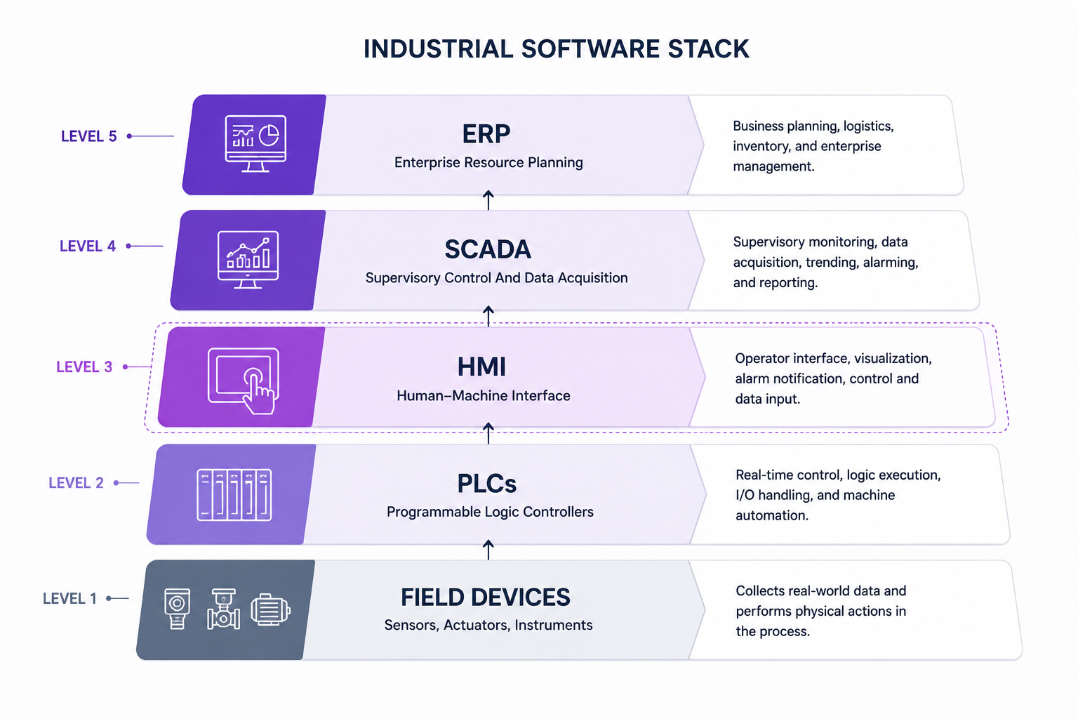
HMIs serve three distinct functional roles depending on deployment depth:
The industrial stack runs: Field Devices → PLCs → HMI → SCADA → MES → ERP. HMI sits at the critical junction between machine-level control and enterprise reporting. Errors at this layer propagate both downward (wrong setpoints to PLCs) and upward (corrupted data to MES).
HMI vs. SCADA vs. DCS — Functional Comparison Matrix
| Dimension | HMI | SCADA | DCS |
| Primary role | Operator interface at machine/line level | Supervisory monitoring across multiple HMIs | Distributed process control across plant |
| Data scope | Single machine or line | Multiple sites, historians, remote assets | Entire plant process loop |
| Real-time control | Yes (PLC-bound) | Limited (monitoring + command) | Yes (native to process control) |
| Connectivity | OPC UA, Modbus, Profibus, MQTT | OPC DA/UA, DNP3, IEC 104 | Proprietary fieldbus + OPC UA |
| Typical deployment | Panel PC, embedded display | Server + workstation cluster | Dedicated DCS hardware suite |
| US vendor examples | Rockwell, Siemens, Schneider | Wonderware, Ignition, GE iFIX | Emerson DeltaV, Honeywell Experion |
HMI architecture is where most projects either build a strong foundation or inherit a decade of technical debt. Choosing the wrong architecture for your hardware target, latency requirements, or plant topology is one of the most expensive mistakes in industrial software development.
Every robust HMI system is built across four layers:
Architectural failure often begins here: teams over-invest in the presentation layer while neglecting communication layer latency and data layer scalability.
Bare-metal: Maximum determinism, minimum overhead. Used where response times under 10ms are mandatory. Requires deep firmware expertise and limits UI complexity.
RTOS (FreeRTOS, Zephyr, QNX): Task scheduling with priority control. Enables more complex UIs while preserving real-time guarantees. Standard for safety-critical embedded HMIs in medical devices and automotive.
Linux-based (Yocto, Buildroot): Full OS stack with modern embedded software development frameworks. Supports Qt/QML, WebAssembly, and containerized applications. Latency is less deterministic but acceptable for most visualization-dominant use cases.
Single-panel HMIs don’t scale to multi-line or multi-site operations. Distributed HMI architectures centralize tag management and alarming while distributing display nodes across the plant floor.
Key design decisions in distributed HMI:
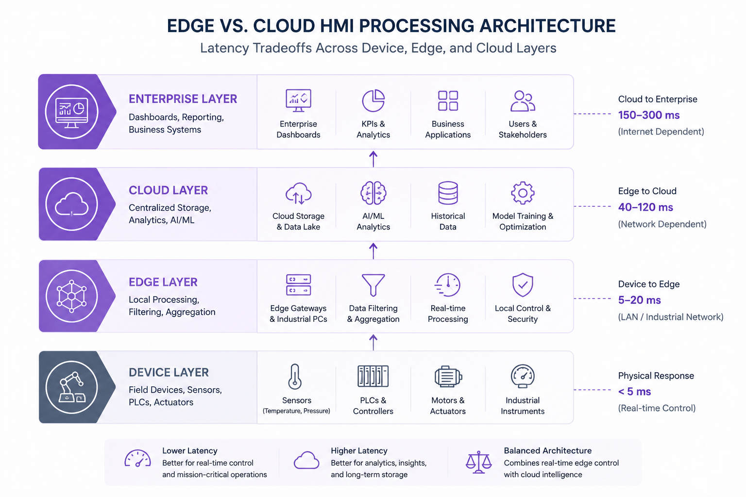
Cloud-connected HMI architectures enable enterprise dashboards, remote monitoring, and AI analytics — but introduce latency that local control loops cannot tolerate. The practical resolution used in most modern US manufacturing deployments:
Industrial UX is a distinct discipline. The ISA-101 standard — not Material Design or Apple HIG — governs display design for process control environments. Violating these conventions doesn’t just produce poor UX; it creates safety risk.
ISA-101 (Human Machine Interfaces for Process Automation Systems) provides the definitive design standard for process industry HMIs in the US. Key requirements:
ISA-101 Color Coding Standards vs. Common HMI Design Violations
| Element | ISA-101 Recommendation | Common Violation |
| Background | Medium gray (approx. #808080) | White or black backgrounds |
| Normal state | Gray/muted tones | Bright colors on all elements |
| Abnormal/alarm | High-contrast yellow, red | Uniform red for all alerts |
| Primary text | Dark on light, high contrast | Low-contrast text on colored backgrounds |
| Animated elements | Reserved for active alarms | Decorative animations throughout |
Alarm fatigue is a documented safety risk. In high-volume process plants, operators may face thousands of alarm events per day — the majority of which are nuisance alarms that mask the critical few.
Effective HMI design addresses this through:
Panel PC screens in steel mills face direct sunlight glare, vibration, and operators wearing heavy gloves. Design requirements that follow: touch targets minimum 15mm x 15mm, 1000-nit display brightness for outdoor/high-lux environments, resistance to accidental actuation through minimum hold-time requirements for critical controls.
The most common HMI design failure isn’t technical. It’s a process failure: engineers design for their own mental model of the system rather than for operator task workflows.
Operator-centered design starts with task analysis:
Engineer-centered designs expose all available data. Operator-centered designs expose only the data needed for the next decision.
AI integration in HMI is moving past the pilot stage. Leading US manufacturers are deploying production-grade AI capabilities at the interface layer — not just in back-end analytics systems.
Traditional HMIs display what is happening. AI-augmented HMIs surface what is about to happen.
Pattern: Edge inference models (deployed on the same hardware as the HMI runtime or on a co-located edge server) process sensor streams in real time and push anomaly scores, predicted remaining useful life (RUL) values, and deviation alerts directly into the HMI display layer.
The UX challenge: surfacing predictions without overwhelming operators. Effective implementations use subtle visual cues (amber tinting, trend micro-charts) rather than additional alarm events.
AI models trained on historical alarm-process correlations can filter nuisance alarms, suppress correlated alarm floods, and route critical alerts to the front of operator attention queues.
According to CISA advisories and ISA-18.2 guidance, alarm fatigue is a documented contributor to industrial incidents. AI-assisted alarm rationalization reduces standing alarm counts by 40–70% in documented deployments, without reducing safety-critical alert coverage.
The two dominant protocols for IIoT-to-HMI data integration in US industrial environments:
In automotive cockpit HMI and collaborative robotics applications, natural language and gesture interaction are moving from concept to production.
A 2025 narrative review in Applied Sciences identifies information overload, AI/AR integration, and cognitive safety as the primary challenges in next-generation automotive HMI design — reinforcing the need for multimodal interaction that reduces operator visual attention demands.
Voice command HMIs in industrial settings face noise floor challenges. Current deployments combine directional microphones, noise-canceling preprocessing, and constrained command vocabularies (rather than open NLP) to achieve reliable operation.
AR-based HMI overlays are gaining traction in field service and aerospace maintenance, projecting equipment status, maintenance procedures, and live sensor data into the operator’s visual field via smart glasses or tablet-based AR.
These systems represent an architectural extension of traditional HMI — the display layer migrates to the field, while data and control layers remain centralized.
A structured development process is the clearest differentiator between HMI projects that commission cleanly and those that spend months in rework cycles.
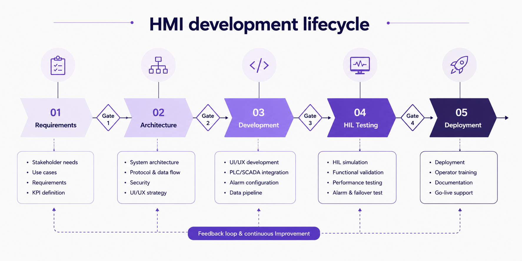
Requirements for HMI software must capture two parallel dimensions:
Architecture decisions made in Phase 2 constrain every subsequent phase. Key decisions:
Development in HMI projects combines traditional software engineering with control system integration:
HIL testing runs the HMI software against simulated PLC outputs before commissioning on live equipment. This catches:
Skipping HIL testing to save time is a false economy. Bugs found during live commissioning in an operating plant cost 10–20x more to fix than bugs found in a simulation environment.
Commissioning includes not just software go-live but the operational transfer: operator acceptance testing, training program delivery, and documentation handover. HMI projects that treat training as an afterthought consistently underperform on adoption and safety metrics.
Waterfall aligns with formal safety certification processes (DO-178C, IEC 61508) where each phase must produce documented artifacts before the next begins. Non-negotiable in aerospace and safety-instrumented system HMIs.
Agile/iterative works well for visualization-layer HMIs where requirements evolve and operator feedback loops are valuable. Not appropriate where certification artifacts require phase-gate sign-off.
Many enterprise HMI projects use a hybrid: waterfall architecture and requirements phases, iterative development and testing sprints.
HMI Platform and Technology Stack Selection
Platform selection is one of the highest-leverage decisions in an HMI project. The wrong platform locks you into proprietary ecosystems, limits scalability, and drives up long-term maintenance cost.
Inductive Automation Ignition is the most significant disruptor in the US industrial HMI market. Unlimited tag licensing, browser-based deployment, Python scripting, and strong OPC UA support have made it the default choice for modern US integrators and system architects.
Node-RED is popular for IIoT prototyping and lightweight HMI dashboards where visual programming is sufficient. Not suited for production safety-critical applications.
HMI Platform Comparison Matrix for Industrial Software Development
| Platform | License Cost | Tag Scaling | Protocol Breadth | Best For |
| Rockwell FactoryTalk | High (per-tag) | Limited | AB-ecosystem native | Rockwell PLC environments |
| Siemens WinCC | High | Moderate | Siemens S7 native + OPC | Multi-site process plants |
| Schneider EcoStruxure | Moderate-High | Good | Multi-protocol | Energy + multi-vendor plants |
| Inductive Automation Ignition | Moderate (flat) | Excellent | OPC UA, MQTT, broad | Modern US manufacturing |
| Qt/QML custom | Dev cost only | Unlimited | Custom drivers | Embedded, automotive, custom |
| React + WebSockets | Dev cost only | Unlimited | Custom | Web HMI, dashboards |
HMI endpoints are the most commonly targeted entry point for ICS cyberattacks. CISA advisories consistently identify internet-exposed HMI systems as critical vulnerabilities in US critical infrastructure. Security cannot be retrofitted — it must be designed in.
CISA’s ICS advisories consistently identify the following HMI-specific threat vectors:
IEC 62443 is the international standard for industrial automation and control system (IACS) cybersecurity. For US manufacturers, compliance is increasingly required by:
Best practice for remote HMI access in 2026:
HMIs deployed in FDA-regulated manufacturing environments must comply with 21 CFR Part 11, which governs electronic records and electronic signatures. Key HMI-specific requirements:
Industrial HMI Compliance Framework Comparison
| Framework | Primary Sector | HMI Requirement Focus |
| IEC 62443 | All industrial | Network segmentation, Security Levels, access control |
| NIST CSF | US critical infrastructure | Identify, Protect, Detect, Respond, Recover functions |
| FDA 21 CFR Part 11 | Pharma / life sciences | Audit trails, e-signatures, system validation |
| NERC CIP | Energy / utilities | Cyber asset identification, access management |
| DO-178C | Aerospace / defense | Software lifecycle, verification, certification levels |
| ISA-101 | Process industries | Display design standards, alarm management |
No HMI overview is complete without a frank discussion of why projects fail. These aren’t edge cases — they’re the recurring patterns that experienced integrators encounter across industries.
Requirements documents filled with tag lists and protocol specifications are necessary but insufficient. The missing piece is always operator task analysis: the sequence of decisions an operator makes, the information each decision requires, and the time pressure under which decisions occur.
HMIs built without operator task analysis consistently fail acceptance testing and require expensive UI rework after deployment.
Legacy PLC systems running Modbus RTU, DH+, or proprietary fieldbus protocols don’t communicate natively with modern HMI platforms designed around OPC UA or EtherNet/IP. Protocol conversion adds latency, complexity, and failure points.
The fix — protocol gateways or software adapters — works but must be planned and budgeted at architecture phase. Discovering the mismatch at integration phase is a schedule and cost crisis.
The gap between development-environment testing and live plant commissioning is where HMI bugs hide. HIL testing closes this gap, but many projects skip it under schedule pressure — and pay for it in extended commissioning cycles and post-deployment defect resolution.
Adding cybersecurity controls to a deployed HMI system is 3–5x more expensive than designing them in. Network segmentation, encrypted communications, and authentication layers require architectural decisions that cannot be easily retrofitted onto a running system.
CISA’s guidance is consistent: secure-by-design is not optional for new HMI deployments in critical infrastructure.
Single-site, single-line HMI projects frequently become multi-site deployment requirements within 24 months of go-live. Monolithic HMI architectures — where screen templates, tag structures, and alarm configurations are hardcoded to one production line — cannot scale without effectively being rebuilt.
Template-driven development and modular architecture decisions made early in the project eliminate this failure mode almost entirely.
Enterprise HMI deployments don’t stay at pilot scale. The organizations that avoid rearchitecting their HMI infrastructure every 3–5 years are the ones that planned for scale from the start.
Modular design means building HMI screens, tag structures, and alarm configurations as reusable templates rather than one-off implementations. When a new production line is added, the template is instantiated with line-specific parameters rather than rebuilt from scratch.
This approach also supports consistent operator experience across sites — reducing training overhead when operators rotate between facilities.
Centralized: Single tag server and historian serving all display nodes. Simpler management, single point of failure risk. Suitable for single-site deployments with reliable network infrastructure.
Decentralized: Local tag servers at each site or line, synchronized to enterprise historian. More complex, more resilient. Required for multi-site deployments where local operations must continue during WAN outages.
HMI software is still code. Yet many organizations treat it as a configuration artifact managed by file copies on USB drives. At enterprise scale this creates:
Modern HMI development teams apply git-based version control, automated configuration validation, and staged deployment pipelines to HMI software — the same practices that enterprise software teams apply to application code.
HMI requirements vary significantly by sector. Compliance obligations, hardware constraints, communication protocols, and operator workflow patterns differ enough that sector experience — not just HMI platform expertise — matters in vendor selection.
HMI Software Requirements Across Industrial Sectors
| Sector | Key HMI Requirements | Primary Compliance | Common Platforms |
| Manufacturing / Smart Factory | OEE dashboards, line control, alarm management | IEC 62443, ISA-101 | Ignition, WinCC, FactoryTalk |
| Automotive / SDV | In-vehicle HMI, cockpit domain controller, AUTOSAR | ISO 26262, ASPICE | Qt/QML, custom embedded |
| Energy / Utilities | Substation HMI, grid monitoring, SCADA integration | NERC CIP, IEC 61850 | GE iFIX, Ignition, Wonderware |
| Aerospace / Defense | Ruggedized panels, DO-178C certified software | DO-178C, MIL-STD | Custom RTOS, proprietary |
| Healthcare / Medical | FDA-regulated medical device HMI, usability engineering | FDA 21 CFR Part 11, IEC 62366 | Custom, LabVIEW, proprietary |
| Pharma / Life Sciences | GMP manufacturing HMI, electronic batch records | FDA 21 CFR Part 11, GAMP 5 | Wonderware, custom validated |
The SML ISUZU ERP Viewer, developed by Code Brew Labs for one of India’s leading commercial vehicle manufacturers, demonstrates the same scalability and real-time visibility challenges seen in modern industrial HMI systems.
The platform was built to centralize operational data, improve cross-team workflow visibility, and support scalable enterprise reporting across devices and departments. Today, it serves 1,000+ employees with a 4.7/5 average rating while delivering real-time operational dashboards and role-based information access.
Many of the same architectural principles used in enterprise operational software — centralized data flow, scalable visualization layers, and real-time system visibility — directly apply to connected HMI and industrial automation environments.
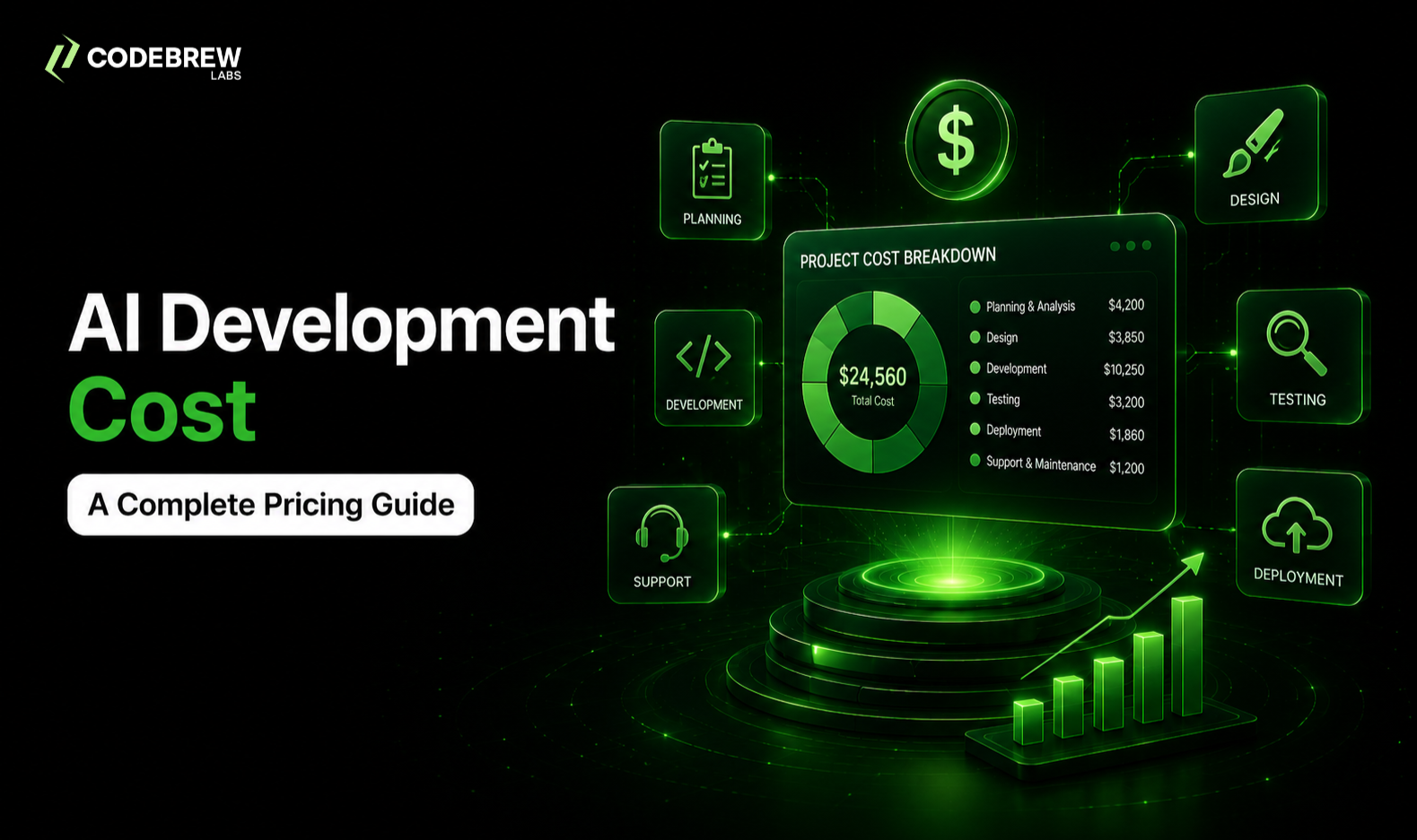
What does HMI software development cost?
US market pricing benchmarks (2025–2026):
Build in-house: Appropriate when your organization has sustained HMI development capability, long-term ownership requirements, and the project volume to justify a dedicated team. Rare outside large manufacturing enterprises.
Off-the-shelf platform: Right choice when your control systems match the platform’s native protocol ecosystem and your requirements fit standard widget libraries. Fastest time to deployment.
Custom development / outsourced: Optimal when hardware targets, compliance requirements, or UI specifications exceed platform capabilities — or when internal capability doesn’t exist. Key evaluation criteria: sector experience, compliance track record, and post-deployment support model.
The case for custom HMI development versus off-the-shelf platforms isn’t about technology preference. It’s about fit-to-requirement:
Q1: What is HMI software development?
HMI software development is the process of designing and building operator interfaces that connect human users with machines, industrial control systems, PLCs, SCADA infrastructure, robotics, and embedded hardware.
It includes real-time visualization, control logic binding, alarm management, and compliance with industrial standards across sectors like manufacturing, energy, automotive, and healthcare.
Q2: What programming languages are used in HMI development?
The language stack depends on the deployment context:
Q3: How much does custom HMI software development cost? US market benchmarks: Simple HMIs run $10K–$15K (single line, standard platform, no compliance requirements). Mid-complexity projects cost $50K–$100K (multi-protocol, custom UI, baseline compliance). Enterprise or safety-critical HMI development starts at $150K and scales with compliance depth, hardware targets, and integration scope.
Q4: What is the difference between HMI and SCADA?
HMI is the operator interface at the machine or production line level — direct interaction with PLCs and local control systems. SCADA is the supervisory layer above HMI: it aggregates data from multiple HMIs across a plant or multi-site operation, adds data historian functionality, and enables remote monitoring and command. An HMI shows you what is happening on one line. SCADA shows you what is happening across the entire operation.
Q5: What are the best HMI software platforms for US manufacturers?
Evaluation criteria: existing PLC ecosystem, network architecture, compliance requirements, and internal engineering capability.
Q6: How is AI being integrated into HMI systems in 2026?
Predictive maintenance overlays surfaced directly in operator displays, AI-driven alarm filtering to reduce alarm fatigue, NLP-based operator query interfaces for diagnostic data, edge inference on embedded displays for real-time anomaly detection, and AR field service overlays combining spatial computing with live equipment data from the HMI data layer.
Q7: What compliance standards apply to HMI software in the US?
Q8: What are the most common reasons HMI software projects fail?
Skipping operator task analysis in requirements, protocol mismatches with legacy PLC systems discovered during commissioning, inadequate hardware-in-the-loop testing, security designed as a retrofit rather than a foundational requirement, and monolithic architecture that cannot scale to additional production lines without full redevelopment.
HMI software projects succeed or fail in the first three weeks — during requirements engineering and architecture design. Getting the data model, protocol strategy, and scalability patterns right before a line of code is written matters more than platforms, screen designs, or feature sets.
At Code Brew Labs, the focus is on building scalable industrial, embedded, and enterprise-grade software systems designed for long-term operational reliability and growth.


 Contact Us
Team Up With Us Today For An Unforgettable Service Experience


 Book Free Consultation